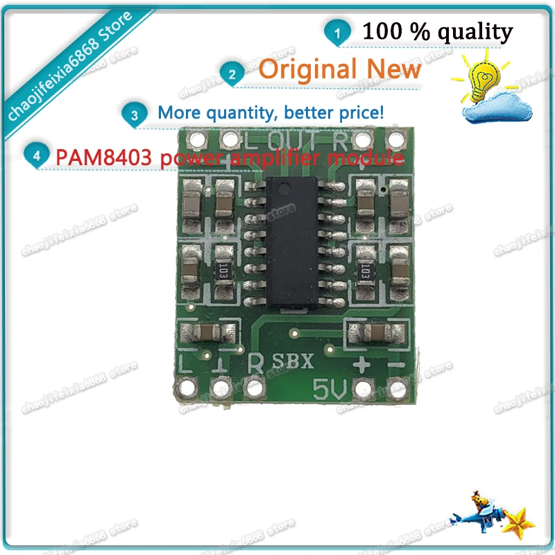
5 шт. - 10 шт./лот! Ультраминиатюрная цифровая усилительная плата PAM8403 мощностью 2 * 3 Вт класса D 2.5 〜 5 В может работать от USB.
128.15


Сохраните в закладки:


*История изменения цены! Указанная стоимость возможно, уже изменилось. Проверить текущую цену - >
| Месяц | Минимальная цена | Макс. стоимость | Цена |
|---|---|---|---|
| Aug-17-2025 | 1482.35 руб. | 1512.89 руб. | 1497 руб. |
| Jul-17-2025 | 1202.53 руб. | 1226.49 руб. | 1214 руб. |
| Jun-17-2025 | 1459.62 руб. | 1488.51 руб. | 1473.5 руб. |
| May-17-2025 | 1447.84 руб. | 1476.88 руб. | 1461.5 руб. |
| Apr-17-2025 | 1155.5 руб. | 1178.31 руб. | 1166.5 руб. |
| Mar-17-2025 | 1424.19 руб. | 1452.52 руб. | 1438 руб. |
| Feb-17-2025 | 1412.52 руб. | 1440.21 руб. | 1426 руб. |
| Jan-17-2025 | 1400.22 руб. | 1428.30 руб. | 1414 руб. |
Новые товары
Характеристики
Описание товара
Power Supply Module Xilinx FPGA Development Board DIY Kit
Prototype PCB NanoPi Development Board Altera FPGA Development Board
Wireless Power Board Wireless Wifi Module

Купила детский вязанный свитер для своей малышки. Свитер яркий и несмотря на то, что осенний, теплый, приятный на ощупь,... Читать отзыв полностью...

Платье очень деликатное и умело подчеркивает все достоинства фигуры, особенно талию. Отлично подойдет как в офис, так и на прогулку... Читать отзыв полностью...

Всё идеально !Теперь у меня есть новые замечательные часы !))Только сегодня забрала их..очень эффектные и красиво смотрятся на руке ))вживую... Читать отзыв полностью...

Нужна прошивка v8.3.2_20180925.105435_akw5 для магнитолы Asottu Z13SLT8060 Android 7.1... Читать отзыв полностью...

Решила заказать своей подруге на День рождения в подарок эти солнцезащитные очки с фиолетовым красивым оттенком. Они сразу подошли ей... Читать отзыв полностью...

Подала заявку на сайте на заказ постельного белья цвета шампанского. В этот же день начали исполнять мой индивидуальный заказ. Через... Читать отзыв полностью...


К сожалению на печатной схеме очень трудно отличить друг от друга значки цветов 28 и 29, хоть бы буквы разные... Читать отзыв полностью...