
Устройство для обнаружения засорения труб устройство трубопроводов детектор
3959


Сохраните в закладки:


*История изменения цены! Указанная стоимость возможно, уже изменилось. Проверить текущую цену - >
| Месяц | Минимальная цена | Макс. стоимость | Цена |
|---|---|---|---|
| Mar-17-2026 | 4196.40 руб. | 4406.92 руб. | 4301 руб. |
| Feb-17-2026 | 4161.13 руб. | 4369.49 руб. | 4265 руб. |
| Jan-17-2026 | 3491.92 руб. | 3666.89 руб. | 3578.5 руб. |
| Dec-17-2025 | 4090.33 руб. | 4295.80 руб. | 4192.5 руб. |
| Nov-17-2025 | 3561.57 руб. | 3739.45 руб. | 3650 руб. |
| Oct-17-2025 | 4020.94 руб. | 4221.45 руб. | 4120.5 руб. |
| Sep-17-2025 | 3984.24 руб. | 4183.23 руб. | 4083.5 руб. |
| Aug-17-2025 | 3949.78 руб. | 4146.69 руб. | 4047.5 руб. |
| Jul-17-2025 | 3914.30 руб. | 4110.86 руб. | 4012 руб. |
Новые товары
Характеристики
Описание товара
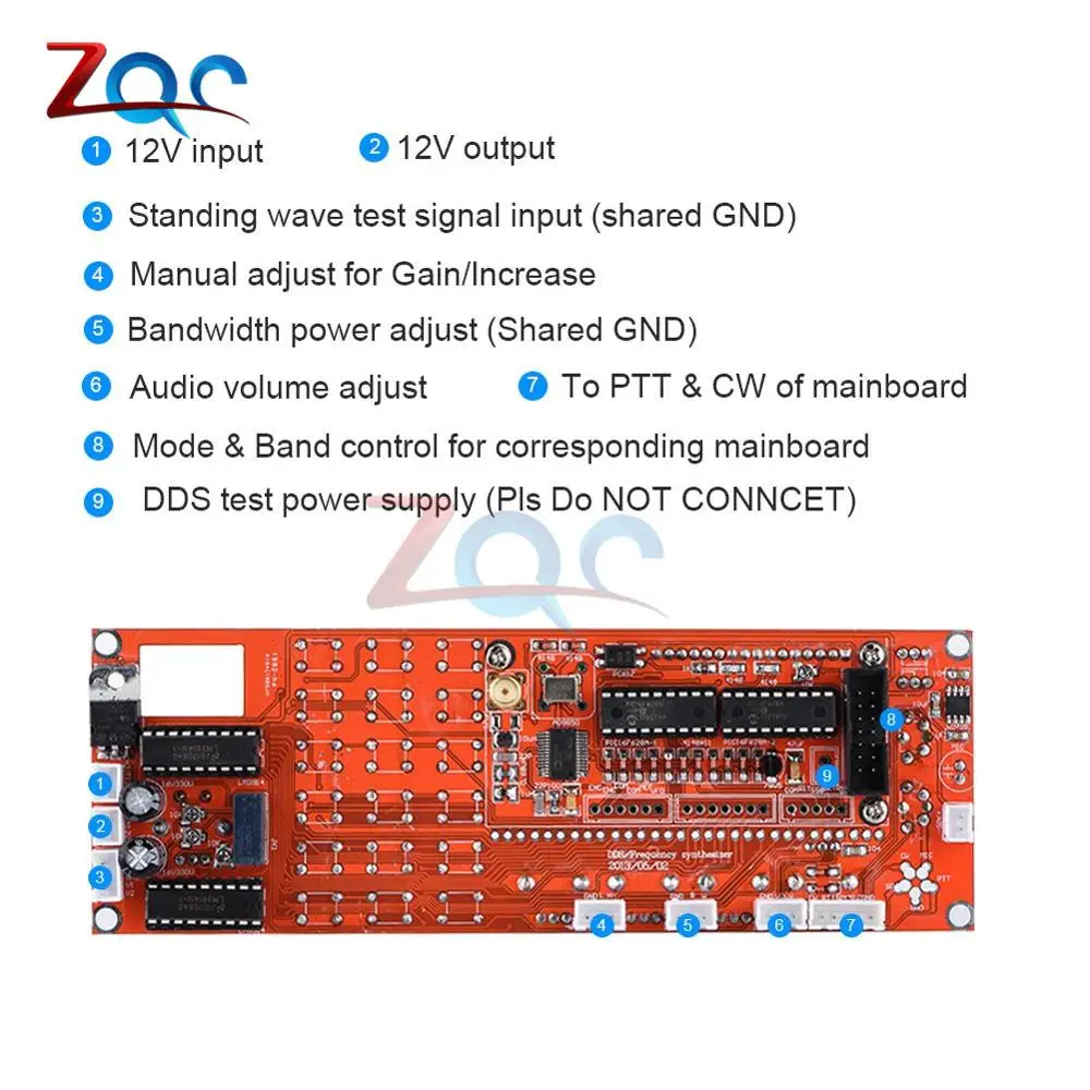
Finished product, DDS, digital direct input frequency, with the volume potentiometer potentiometer, amplifier gain bandwidth potentiometer, AGC potentiometer, S - LED table display, a standing wave - LED table display
1:12 v input
2:12 v output
3: standing wave power into the detection signal.Common ground
4: manual gain control
5: bandwidth power regulation, altogether
Six volume
7: the corresponding motherboard microphones horn PPT and the CW
8: the mainboard control mode and band
9: DDS test power supply, don't welding
Use debug settings
6, the external button wiring methods:
In Fig KB-2 and KB-1 is an external key interface, which is the first leg leftmost respective interface common pin, which were co-phase four feet, their respective functions, such as KB-1: 1 -2 connected to complete work mode control switching functions, such as KB-1: 1-4 is connected to enable adjustment of stepping.
ENC image above coding switch feet, which, under the view of the switch of A contact pin 2 KB-2, and the drawing of B then KB-2 Pin 3, the drawing of C continued on the KB-2 1 foot.
7, on the work mode and band control function
Due to the limited capacity of the microcontroller itself, drive, or external relay operating voltage is different, not directly drive a relay, drivers need to work mode and operating band needs an external drive circuit, a specific circuit can refer to other materials.
8, LCD backlight connection
Taking into account the number of people may use their own configuration LCD display, LED backlight may be because of different polarity, so the PCB, the 15 and 16 feet are vacant, and ask all of you to connect the LCD according to the polarity used.
It provides the LCD backlight connection, 16 feet grounded, 15 feet in series a 51 ohm resistor connected to + 5V power supply is like, if you want to keep off the backlight, you can take a switch to + 5V control.
fficeffice "/>
Two, DDS debugging
The DDS control chip PIC16F628A-1 and PIC16F628A-2 has written VER4.06 program, after all the installation is complete, the access 5V supply, the 10K potentiometer to adjust the contrast, you can see on the screen under normal circumstances character, if not normal, measure the operating voltage of the microcontroller and display section. The set voltage polarity protection, so it will not happen to burn case you die.
If the LCD can not display the characters, please try to exchange PIC16F628A, because the two programs are different chips, follow my number marked on the component installation.
Three, DDS key instructions and steps:
1, a key interface description:
ENC coding switch wiring feet
MEM storage mode conversion
VFO VFO A converted to VFO B, or by a VFO B switch to VFO A.
Conversion SSB operating mode, USB LSB AM CW cycle conversion.
RIT fine-tune the reception frequency.
STEP step adjustment buttons.
CAL function setting button.
Wherein the KB-1 and KB-2 has a common pin, but not ground, please pay attention when installing.
3. Hold down the CAL button, power boot into the initial settings interface, and release the CAL button.
A: ENABLE 6XREFCLE: Set chip clock mode, adjust the frequency encoding switch settings, AD9851 set to 6 octave, AD9850 set to 1 octave, press CAL to enter the next item.
B: DDS-SYSTEM-CLK: the chip operating frequency is set, adjust coding switch to change the value, with the STEP key adjustment step, AD9851 set to 6 multiplier value of active Zhong, AD9850 set to the actual output of the source Restructure value, press CAL to enter the next item.
C: MIN_RX_DDS_FREQ: minimum operating frequency setting, adjust encoding switch to change the value, with the STEP key adjustment step should be set larger than the intermediate frequency value, press CAL to enter the next item.
D: MAX_RX_DDS_FREQ: maximum operating frequency setting, adjust encoding switch to change the value, with the STEP key adjustment step, should be set to 60MHZ or less can be, short press CAL to enter the next item.
E: SSB_OFFSET: SSB mode trim, adjust coding switch to change the value, with the STEP key adjustment step, press CAL to enter the next item.
F: CW_OFFSET: CW operating mode to fine-tune and adjust coding switch to change the value, with the STEP key adjustment step, press CAL to enter the next item.
G: OFFSET_FREQ: MF setting, as set 9MHZ or 10.7MHZ, adjust encoding switch to change the value, with the STEP key adjustment step, press CAL to enter the next item.
H: MULTIPLIER: multiplier setting should be set to 1, press CAL to enter the next item.
I: The display prompts SAVE, automatically save the contents of the above temples and return to normal operation.
Other notes:
1, DDS SYSTEM CLK can be measured by the frequency after 30MHZ active crystal, the measured value is multiplied by 6, the calculated value is set here, if you are using AD9851, initially set to 180 million on the line.
2, OFFSET FREQ intermediate frequency settings can be set to + or -, rotary switch to change the value, hold down the STEP key, then coded rotary switches to adjust the step. In addition the value of the minimum operating frequency plus the intermediate frequency must be greater than zero.
Storage ** ** Frequency
Store the current VFO frequency: Hold MEM button for 1 second, using the encoder selects the channel you want to store. Simultaneously selected, the selected channel original frequency will be displayed on LCD, then, once again hold down the MEM button for 1 second, at the same time return to VFO display a message "SAVING" will be displayed briefly. (Stored) If you decide to return to VFO display or storage, tap MEM key or wait 10 seconds to automatically return. Before using the memory function, make sure that all parameters are correct, this will prevent the wrong message written letter hang.
** ** Use memory channel
When MEM from state to state VFO, an encoder can choose to receive a frequency previously stored,
Tap the MEM key, "MEM 1" will be displayed at the top of the LCD, you can use the encoder to select the channel you want to use, when in MEM mode TX button and RPT key function is normal, but you will not be able to change the encoder frequency, RIT function properly. (You can use the encoder to change the RIT frequency). When the MEM mode, you can not use the setup menu or frequency storage.
In operation, the setup menu will check the correctness of storage, if found to contain an error message, "MEM" display changes to "---", causing this because when you are in the setup menu to change certain parameters afterwards. And then try to store the previous changes. (For example: Assume ffice: smarttags "/> reception frequency memory 30M of 1, if you put MAX RX DDS FREQ frequency to 29M, when you try to use MEM 1, the setup menu will discover 30M reception frequency error in MEN, because It is too high), therefore, the correct approach is, before storage, proper menu settings.
There are two ways to exit the MEM mode, returning the VFO mode:
1) Tap the MEM key, ignoring the use of memory frequency.
2) Hold down the MEM button for 1 second, the right frequency will be copied to VFO.
** Menu settings are stored **
Any change menu settings after MULTIPLIER settings will be stored in EEPROM, and will briefly display "SAVING" message and return to VFO state.
In the Settings menu, (except DDS REF FREQ menu), if, keys, keyboard or encoder no action for 10 seconds, the screen will ignore all the action, return to VFO display).
If the RIT (tuning) gently press, "RIT" will be displayed on the LCD, but the frequency will not change greatly, (RX frequency +/- MAX_RIT_OFFSET frequency range), press the key again RIT, RIT display will disappear and return to RX frequency, and clear RIT frequency.
If the RPT (REPEATER TX offset only by the FM) function in the settings menu open, tap the RPT will display "-RPT" on the LCD, while subtracting from the TX frequency (RPT OFFSET) frequency. Press again, clear the RPT setting, the default REPEATER TX OFFSET is 0KHZ, but it can be changed in the settings menu RPT OFFSET, range 0 to 10MHZ. (Also limited because DDS leaving a 0 to MAX DDS FREQ frequency)
If the RPT function is set to disabled, the RPT function is canceled, at the same time, RPT set frequency will automatically set to 0HZ.
All settings will affect the frequency limits, while recognizing the settings are valid, for example: TX offset plus the RX frequency can not exceed DDS frequency range.
If the step button is pressed, a cursor flashing under the current frequency of the digital, then you can use the encoder selection step.
For example: In 1KHZ stepper, move the cursor after the release, then the change will be a stepping 1K (if rotation is too fast, the system will be detected, stepping beyond the scope settings may remain unchanged.)
At any step set VFO state, it will be stored in EEPROM. (Not stored in the set-up and RIT Settings menu)
Frequency display will follow what the formula:
RX = MULTIPLIER x (RX_DDS_FREQ + OFFSET_FREQ)
TX = MULTIPLIER x (RX_DDS_FREQ + OFFSET_FREQ + TX_OFFSET_FREQ)
The frequency programmed into the DDS, is calculated as shown below.
RX = ABS (RX_DDS_FREQ)
TX = ABS (RX_DDS_FREQ + TX_OFFSET_FREQ)
RX_DDS_FREQ, MIN_RX_DDS_FREQ, MAX_RX_DDS_FREQ, TX_OFFSET_FREQ & OFFSET_FREQ
It may be positive or negative.
Here to tell you a few different examples:
Such as DDS output frequency range of 30M to 40M:
MIN_RX_DDS_FREQ MAX_RX_DDS_FREQ OFFSET_FREQ RX Frequency display range.
30 MHZ 40 MHz 100 MHz = 130 MHz to 140 MHz. \ Note 1
30 MHZ 40 MHz -10 MHz = 20 MHz to 30 MHz. /
-40 MHZ -30 MHz 170 MHz = 140 MHz to 130 MHz. \ Note 2
-40 MHZ -30 MHz 60 MHz = 30 MHz to 20 MHz. /
FT180A setting method used in DDS
Common settings display AD9851 explanation:
ENABLE RPT NO
X6 RECLK X6
DDS SYSTEM CLK 180M
MAX DDS FREQ 65M
MIN RX DDS FREQ 10.701M IF frequency + RIT frequency
MAX RX DDS FREQ 60M
TX OFFSET FREQ 0
MAX RIT OFFSET 1K RIT frequency
OFFSET FREQ -10.700M - IF frequency
MULTIPLIER 1
Fourth, on the band and mode control interface:
The DDS has no direct control mode conversion and the band control device conversion, provided only weak control output level conversion function, the practical application of the circuit, such as relays, the power supply, etc., need individuals increase driving circuit, as this may damage the microcontroller! Associated circuitry can refer friends online DIY machine example.

Достаточно стильные часы за свою цену. Отлично подходит практически под всю мою одежду постельных тонов. Качество выполнения на хорошем уровне.... Читать отзыв полностью...

Всегда мечтал приобрести некую прикольную штучку для своего душа. После нескольких часов поиска наткнулся на данный товар... Светодиодная насадка мне... Читать отзыв полностью...

Шкбку из натуральной овчины заказывала для себя. Доставили оперативно, как раз успели дл зимних холодов. Шуба легкая, качественно пошитая. На... Читать отзыв полностью...

Для шумоизоляции деревянного пола в квартире решила заказать в гостиную комнату теплый и мягкий зимний детский коврик. А сделала... Читать отзыв полностью...

Подала заявку на сайте на заказ постельного белья цвета шампанского. В этот же день начали исполнять мой индивидуальный заказ. Через... Читать отзыв полностью...

Не раз заказывала одежду себе и детям с этого сайта, всё приходит вовремя, без задержек. Размеры всегда уточняются, ещё не... Читать отзыв полностью...


Так, я бы сказал выглядит "старинно" или наверное, как сейчас говорят "винтажно"! Его ещё можно дополнить, а тут по своей... Читать отзыв полностью...